The term industrial valve refers to one of the most critical components in any fluid-handling system. For a manufacturer of pumps, valves or compressors, it is not enough to simply know “what it is”: it is essential to understand how it behaves under pressure, what service life it offers, and what risks are taken if machining, welding or testing are not carried out properly.
In this article you will find a technical overview aimed at OEMs and purchasing/engineering departments: what an industrial valve is, which types exist, which components are most sensitive and, above all, how a partner like Asimer Group can help you ensure precision, repeatability and traceability in your projects.
What is an industrial valve and in which sectors is it used?
An industrial valve is a mechanical device that opens, closes or modulates the flow of a fluid (liquid or gas) in a process line. Its role is not only to “let flow or shut off”, but to do so:
- Within defined pressure and temperature ranges.
- With a specified level of leak tightness.
- With an operating torque compatible with the actuator.
- With acceptable repeatability over thousands of cycles.
This is why, for an OEM, it is not just a catalogue product; it is a critical element for safety and efficiency.
Industrial valves appear in practically all the sectors you operate in:
- Oil & Gas: process lines, manifolds, bypasses, flare systems…
- Petrochemical: corrosive fluids, polymers, services with deposition or abrasion.
- Naval: cooling circuits, seawater, fuel, ballast, auxiliary systems.
- Cryogenics: very low-temperature services alongside equipment such as the centrifugal pump and cryogenic valves.
- Water treatment and desalination: pumping networks, filtration, dosing.
- Nuclear: maximum requirements in dimensional traceability, certificates and testing.
In extreme applications for example, in cryogenics applied to LNG or even in cryogenic applications in the aerospace industry the performance of the industrial valve depends directly on machining precision, material, coatings and the quality of the welded joints.
Main types of industrial valves and their applications
Not all valves perform the same function or withstand the same service conditions. Among the most common in your projects:
- Gate valve: good on/off shut-off, not well suited for fine regulation.
- Globe valve: designed for flow control with more controlled pressure drops.
- Ball valve: fast shut-off, high flow coefficient, widely used in Oil & Gas.
- Butterfly valve: lightweight, compact, ideal for large diameters and water or auxiliary services.
- Check valve: prevents reverse flow and protects pumps and equipment.
- Plug valve: suitable for line switching or multi-way configurations.
- Needle control valve: very fine regulation in small flow rates or high-pressure services.
If you need a broader view of valve families, functions and selection criteria, you can go deeper into types of industrial valves or into the industrial applications of butterfly valves when weight, space and operating torque are decisive.
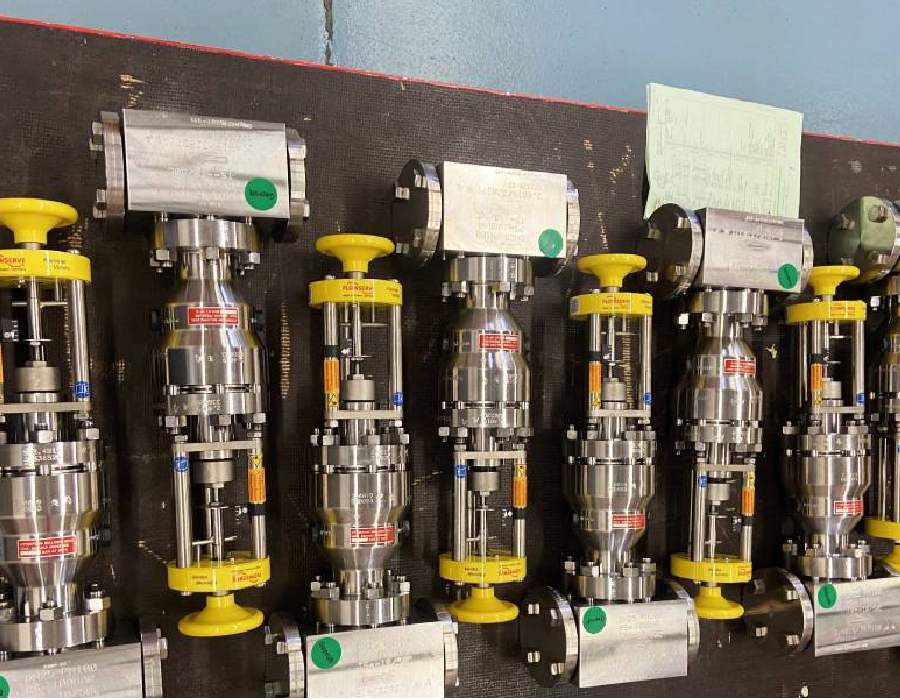
Key components of an industrial valve and machining requirements
From the machining and metrology point of view, an industrial valve can be broken down into several critical elements:
- Body
This is the main housing of the valve and constitutes its external structure. It withstands system pressure and connects to the pipeline. It can have different configurations depending on the valve type (spherical, cylindrical, angular, etc.) and is usually made of carbon steel, stainless steel, bronze, or other materials depending on the working environment. In many industrial applications, the reliability of the valve depends directly on the machining of industrial valve bodies, since this component concentrates critical areas such as sealing faces, seat interfaces, alignment diameters and gasket surfaces that determine the tightness and dimensional stability of the entire assembly. - Obturator or Disc
This is the movable component that regulates the fluid flow. Its design varies depending on the valve type: it can be a ball (ball valve), a cone (globe valve), a flat gate (gate valve), or a rotating disc (butterfly valve). The disc is actuated by a rod or shaft, and its movement allows the flow to be modulated, blocked, or permitted. - Seat
This is the surface on which the disc rests when the valve is closed. It must ensure tight sealing and resist wear caused by fluid friction. Seats can be metallic, soft (Teflon, EPDM), or coated, depending on the service type. - Stem or Shaft
It transmits motion from the actuation mechanism (manual, pneumatic, hydraulic, or electric) to the disc. It can be rising or non-rising and must ensure smooth and precise movement. - Bonnet
This is the upper part of the body, allowing access to the valve interior for maintenance. It seals the assembly using packing or O-rings and may include a gland follower. - Gaskets and Seals
These ensure sealing between the different parts of the valve, preventing both external and internal leaks. Their material and design must be compatible with the fluid and the operating conditions (pressure, temperature, and chemical composition).
Each of these areas requires strict tolerances, surface roughness and alignment. For example:
- Coaxiality between seats and the disc/closure shaft.
- Flatness of gasket faces.
- Controlled roughness on contact surfaces.
All this must be verified with suitable measuring instruments (CMM, measuring arm, gauges, bore meters) within a climate-controlled metrology room. In Industry 4.0 environments, this information is integrated into dimensional spreadsheets and control plans that allow you to demonstrate traceability to audits and end customers.
Evaluating external suppliers for critical valve component machining?
Before outsourcing machining, welding or inspection, make sure your supplier can control the technical factors that affect sealing performance, dimensional accuracy, traceability, QA documentation and project risk.
Request our Supplier Evaluation Checklist for Critical Valve Component Machining and review the key points before choosing a technical partner.
Request the checklistHow Asimer Group machines and verifies an industrial valve
This is where theory becomes reality.
Asimer Group does not manufacture complete valves; it positions itself as a strategic partner for CNC machining and welding of critical industrial valve components for demanding OEMs.
Typical operations include:
- Machining of bodies, covers and bonnets from castings or forgings.
- Finishing of seats, sealing areas and guiding diameters.
- Machining of stems and discs with tight tolerances.
- Hard-facing overlays using TIG, MIG, automatic MIG or PTA welding in high-wear areas.
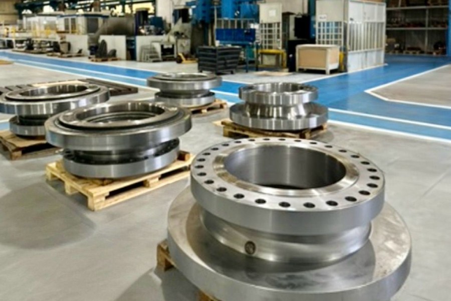
This is possible thanks to:
- Our CNC technology: we work with large-capacity machining centres and CNC lathes capable of handling large industrial valve bodies and covers.
- Chip-removal machining strategies tailored to each alloy.
- Specialised equipment such as the Trevisan machining centre, ideal for large-size bodies.
In large-volume projects or short, repeatable series, the goal is not only to meet the drawing, but to help you optimise machining costs for pumps and valves without sacrificing tolerances or lead times.
If you are assessing new partners for the machining or welding of industrial valve components, we can review drawings, materials and volumes with you.
Contact with our technical team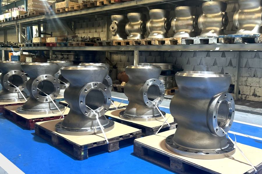
Testing, non-destructive examination and validation of industrial valves
An industrial valve is not “ready” when it leaves the machining centre. Before it goes into service, OEMs and EPCs require:
- Pressure tests (hydrostatic or pneumatic).
- Dimensional inspection according to drawing and specification.
- Functional tests (operating torque, tightness, internal/external leakage).
- Visual inspection in critical areas.
To detect surface or internal discontinuities without damaging the part, non-destructive testing (NDT) is applied: liquid penetrant, magnetic particle, ultrasonic testing, etc. Among these, liquid penetrant testing is especially useful on seats, hard-faced areas or weld beads.
If you need to go one step further in regulatory compliance, it is essential that your partner has personnel with recognised certification, such as that described in How non-destructive testing certification drives industrial quality, and that they know how to select the right method among the different types of non-destructive testing.
Corrosion, coatings and welding in industrial valves
Corrosion is one of the main causes of failure in an industrial valve, especially in Oil & Gas, petrochemical, seawater or chemical services. To reduce this risk, several factors come into play:
- Selection of the right alloy (stainless steels, duplex, super duplex, special alloys).
- Internal design that avoids dead zones and turbulence.
- Coatings and surface treatments.
In this field, it is essential to understand the different types of coatings for industrial valves in extreme environments: epoxy, ceramic, metallic, PTFE, etc., each with its own temperature range, chemical resistance and service life.
When damage is concentrated in localised areas, the solution lies in welding interventions for corrosive environments, selecting the appropriate filler material and process (for example, using TIG welding to maintain metallurgical continuity and the properties of the base material).
By applying these strategies correctly, you not only extend the service life of the industrial valve, but also help reduce the carbon footprint in industrial pumps and valves by avoiding premature replacements and unplanned shutdowns.
Maintenance and reliability strategies for industrial valves
The reliability of an industrial valve does not depend only on how it was machined and tested at the beginning, but on how it is integrated into a global maintenance strategy.
More and more plants are moving from a reactive approach to a data-driven one, as detailed in:
- Predictive machining maintenance vs corrective: which strategy reduces more failures and costs in industrial components?
- Predictive maintenance services for pumps and valves: CNC machining and specialised welding
- Machining and welding for predictive industrial maintenance: solutions for pumps, valves and compressors.
Applying predictive maintenance to industrial valves involves:
- Monitoring operating conditions (pressure, temperature, cycles, vibration).
- Analysing failure patterns in seats, stems, shafts and welded areas.
- Planning interventions before the failure occurs.
In sectors that operate industrial pumps and valves in parallel, such as naval, water treatment or nuclear, this approach makes it possible to minimise downtime, improve the performance of the industrial pumps in the system and extend asset life.
Are you reviewing your supplier base for machining, welding or hard-facing of industrial valves? We can analyse a specific case (drawing, material, annual volume) and propose a technical and economic solution.
Request a technical assessmentIndustrial valve FAQs
Why is dimensional accuracy so critical in an industrial valve?
Because small deviations in seats, the disc/closure element or guides can cause leaks, closing problems, high operating torque or premature wear. Hence the importance of control with measuring instruments in a dedicated metrology room.
What is the difference between a standard industrial valve and one for severe service?
In severe service environments (for example, cryogenic applications or sectors that use large-size valves) the requirements include:
- Special materials.
- Specific coatings.
- Additional testing.
- Advanced machining processes such as CNC machining of switch plug valves for refineries, with tighter tolerances and reinforced dimensional control.
What can Asimer Group offer to a valve manufacturer?
A partner like Asimer Group offers:
- CNC machining capacity and machining-based production for bodies, covers, stems and discs.
- Experience in welding and hard-facing in high-wear areas.
- Integration of CNC technology, advanced metrology and Industry 4.0 into quality control.