Measuring instruments in industrial metrology are not just “tools”: they are the point where a machined part is confirmed as compliant with the drawing, tolerances and OEM requirements or becomes a hidden cost through rework, rejections, delays or disputes.
In critical components such as casings, covers, shafts, impellers, valve bodies or trims, dimensional control has a direct impact on quality, assembly and service performance.
For pump, valve and compressor manufacturers, reliable measurement can help reduce:
- Rework and fit-up adjustments.
- Incoming rejections from the OEM.
- Assembly problems.
- Leakage risk.
- Cavitation or vibration issues.
- Documentation gaps during audits.
Measuring well is not enough. You need a stable manufacturing process, a defined inspection method, calibrated measuring instruments and documented metrological traceability.
In critical parts, that stability depends on the connection between CNC machining, precision machining, welding, metrology and quality inspection.
If you are reviewing drawings, tolerances or dimensional reports for critical machined components, our technical team can assess your dimensional control requirements.
The importance of industrial metrology in pump and valve manufacturing
Metrology is the science of measurement. In industrial production, its objective is simple to define but difficult to guarantee: obtain precise, repeatable and traceable results.
In the manufacturing and verification of pump and valve components, industrial metrology helps confirm that:
- Parts are truly within tolerance.
- Critical dimensions are not assumed, but verified.
- Inspection does not depend only on operator judgement.
- Measurement results can be documented and audited.
- Dimensional deviations are detected before they become field problems.
Traditionally, metrology is divided into three main branches:
- Scientific metrology: standards, units and measurement references.
- Legal metrology: measurement related to trade, regulation and consumer protection.
- Industrial metrology: measurement applied to manufacturing, calibration, verification, quality control and process capability.
In Industry 4.0 environments, industrial metrology is no longer just a final inspection stage. Dimensional measurement data can support machine corrections, process stability, maintenance decisions and continuous improvement.
When measurement is well integrated, dimensional data becomes an early-warning signal.
Measuring instruments and dimensional control after machining and welding
In CNC machining, measuring instruments connect the drawing to the real part. Without measurement, an H7 tolerance, flatness requirement, concentricity value or surface roughness specification remains only a theoretical requirement.
That is why measuring instruments for quality control are essential in dimensional control for machined parts, especially when the component includes sealing surfaces, bearing housings, flanges, shafts or other tolerance-critical areas.
The same applies to welding. After material deposition, repair, overlay or machining of functional areas, dimensional verification is essential to confirm that critical features have not been distorted.
This is especially relevant in demanding applications such as:
- Oil & Gas.
- Cryogenics.
- Petrochemical.
- Naval.
- Desalination.
- Water treatment.
- Components operating under pressure, corrosion or thermal stress.
In these environments, the combination of machining, welding and measurement must work as one controlled system. If one stage fails, the risk moves downstream to assembly, testing or field operation.
That is why dimensional control after technical welding and TIG welding can be just as important as the welding process itself.
Direct vs. indirect dimensional measurement
In industrial metrology, two measurement approaches are commonly used: direct measurement and indirect measurement.
Direct measurement
Direct measurement means the dimension is read directly from the instrument. Typical examples include calipers, micrometers, dial indicators, bore gauges, CMMs and 3D measuring arms.
It is fast and flexible, but it requires:
- Controlled contact points.
- Correct measuring force.
- Clean and stable surfaces.
- Proper part support.
- Temperature control when dimensions are critical.
- A defined procedure to reduce operator variability.
Indirect measurement
Indirect measurement compares the part against a reference standard. Examples include gauge blocks, rings, plug gauges or go/no-go gauges.
This approach is especially useful when the same dimension is repeated and the objective is to reduce variability in recurring inspections.
In both cases, the key is not only the instrument. The key is the measurement strategy:
- What must be measured?
- Which instrument is appropriate?
- How often should it be checked?
- What is the acceptance criterion?
- What action is taken when a result shows drift?
That is when metrology stops being “just measuring tools” and becomes a quality control system.
Dimensional measurement errors: typical causes and how to prevent them
Dimensional measurement errors can occur even with good equipment if the system isn’t properly defined.
Typical sources of error include:
Systematic errors
These errors repeat in the same direction. They may come from:
- An instrument out of adjustment.
- An incorrect procedure.
- Measuring conditions different from the reference.
- Lack of calibration or verification.
They are reduced through calibration, defined procedures and periodic checks.
Random errors
These are small, uncontrolled variations caused by factors such as:
- Vibration.
- Unstable part support.
- Contact variation.
- Micro thermal fluctuations.
- Operator variability.
They are reduced through stable conditions, training and repeated measurements on critical dimensions.
Technique and usage errors
These are common in daily production:
- Excessive micrometer force.
- Incorrect reading.
- Poor part positioning.
- Dirty measuring surfaces.
- Wrong instrument selection.
Temperature and deformation
In industrial metrology, dimensional measurement is commonly referenced around 20°C because both the part and the instrument expand with temperature. Measuring a part while it is still hot from machining can transfer the error into the measurement result.
When material integrity also needs to be verified, dimensional inspection can be complemented with non-destructive testing and, when required, techniques such as liquid penetrant testing.
Geometry plus integrity means fewer surprises in assembly, testing and service.
Tolerances, drawings and OEM requirements: what must be controlled
In pump and valve components, drawings usually combine:
- Nominal dimensions.
- Tolerances.
- Functional surfaces.
- Critical fits.
- Surface roughness requirements.
- Geometric tolerances.
- Inspection criteria.
- Documentation requirements.
Concepts that quickly create problems if not controlled include:
- Fits and tolerances.
- Runout.
- Flatness.
- Parallelism.
- Concentricity.
- Alignment.
- Surface roughness.
- Critical housing dimensions.
- Sealing surfaces.
For purchasing, engineering and quality teams, the key question is not only:
“What measuring instrument do you use?”
The real questions are:
- Can you prove that the dimension is controlled?
- What happens when a result indicates drift?
- Is there repeatable and auditable evidence?
- Are instruments calibrated and identified?
- Can the supplier provide dimensional reports when required?
Download the supplier evaluation checklist for dimensional control
Use this checklist to evaluate whether a machining and welding supplier can control critical dimensions, calibration, traceability and documentation for pump, valve and compressor components.
Request the checklistTypes of measuring instruments used in industrial metrology
The following table summarizes common measuring instruments used in industrial metrology, what they are used for and why they matter in the control of machined components.
In practice, industrial measuring instruments and measuring instruments for machining are selected according to the feature being inspected, the required tolerance, the material, the geometry of the part and the level of evidence requested by the OEM.
| Measuring instrument | Main use | Industrial application | Risk if poorly controlled |
|---|---|---|---|
| Caliper | External, internal and depth measurements. | Quick checks on machined parts, covers, shafts and simple features. | Incorrect readings, poor repeatability or acceptance of out-of-tolerance parts. |
| Micrometer | High-precision external or internal measurements. | Shafts, fits, diameters and tolerance-critical dimensions. | Fit-up issues, excessive clearance or assembly problems. |
| Dial indicator | Runout, alignment and small dimensional variations. | Rotating components, shafts, housings and assembly checks. | Vibration, misalignment or premature wear. |
| Bore gauge | Internal diameters and bores. | Bearing housings, valve bodies, seats and internal fits. | Poor fit, leakage risk or functional failure. |
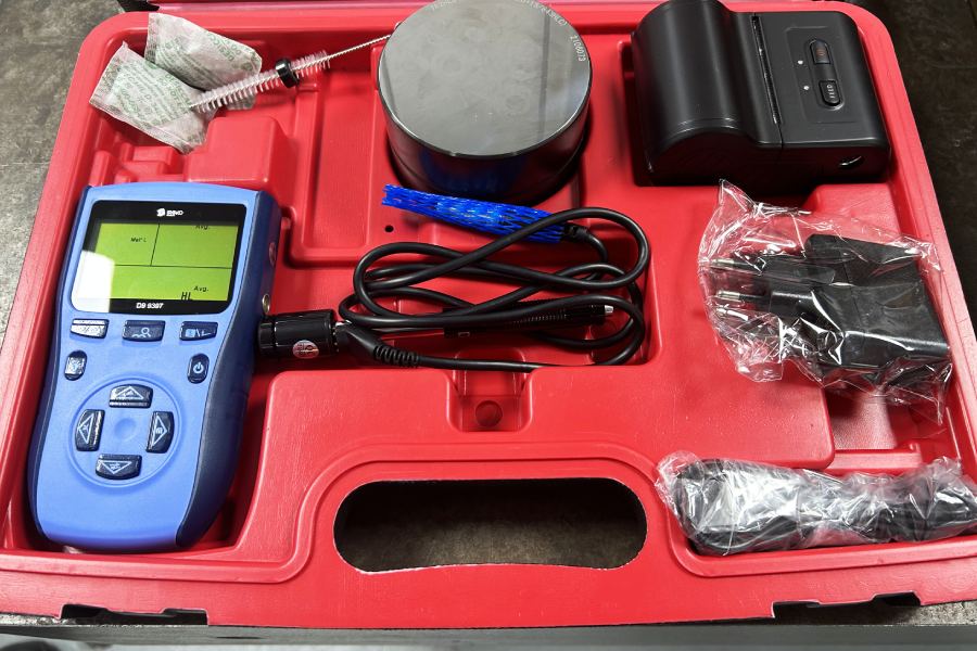
| Hardness tester | Material or surface condition verification. | Components requiring material control or surface treatment validation. | Incorrect material condition or premature wear. |
| CMM | Complete dimensional inspection and reports. | Complex geometries, critical tolerances and OEM documentation. | Lack of traceable evidence or incomplete dimensional verification. |
| 3D measuring arm | Flexible dimensional inspection of large or complex parts. | Pump and valve components, castings, welded parts and machined assemblies. | Undetected deviations in large or complex geometries. |
IMEs at Asimer Group: Metrology room, equipment, and dimensional reports
Measurement integrated into quality and process
At Asimer Group, measurement is integrated into the quality control system and the manufacturing process. When an OEM requires verification and evidence, what truly makes the difference is having a consistent environment, method, and traceability.
Metrology room and controlled conditions
Asimer Group has its own Metrology Room, where:
- The most critical product dimensions are measured (pump and valve components machined in the Production Department).
- Key IMEs are maintained at the required temperature and humidity (a critical condition for reliable dimensional measurement).
- Periodic calibrations are performed on the IMEs that support dimensional control.
Key IMEs used for dimensional control
Among the most important IMEs for controlling parts and processes, the following stand out:
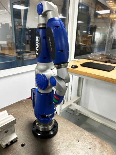
Measuring arm: for flexible inspection of complex-geometry parts.
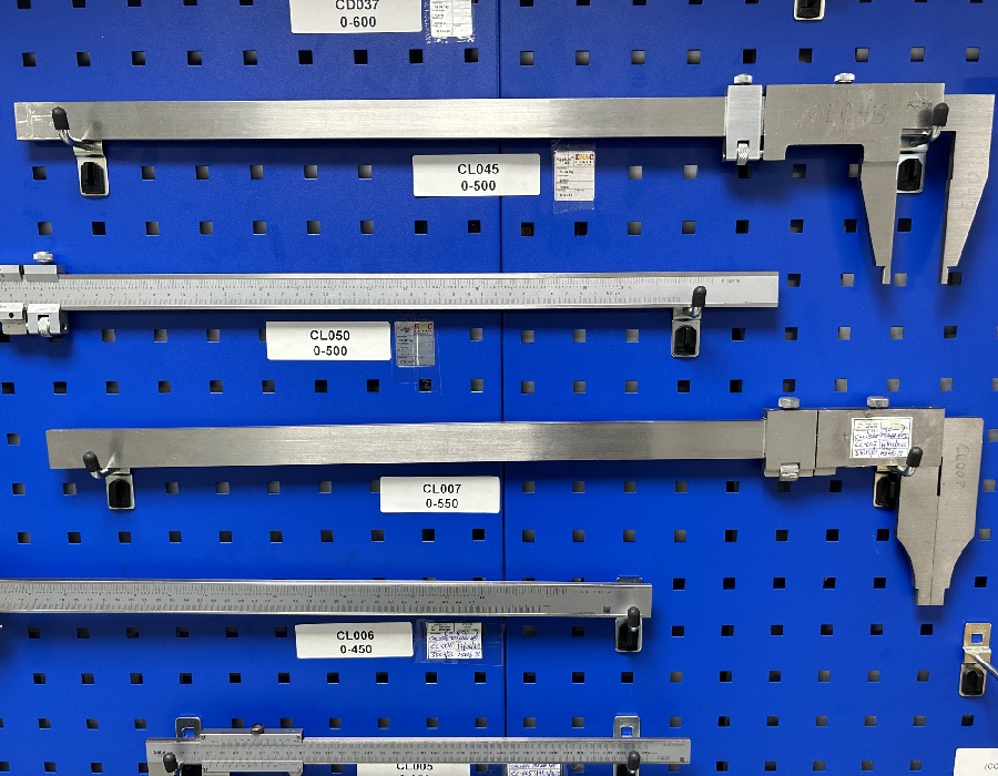
- Gauges or foot of king: quick verification of internal, external, and depth measurements.

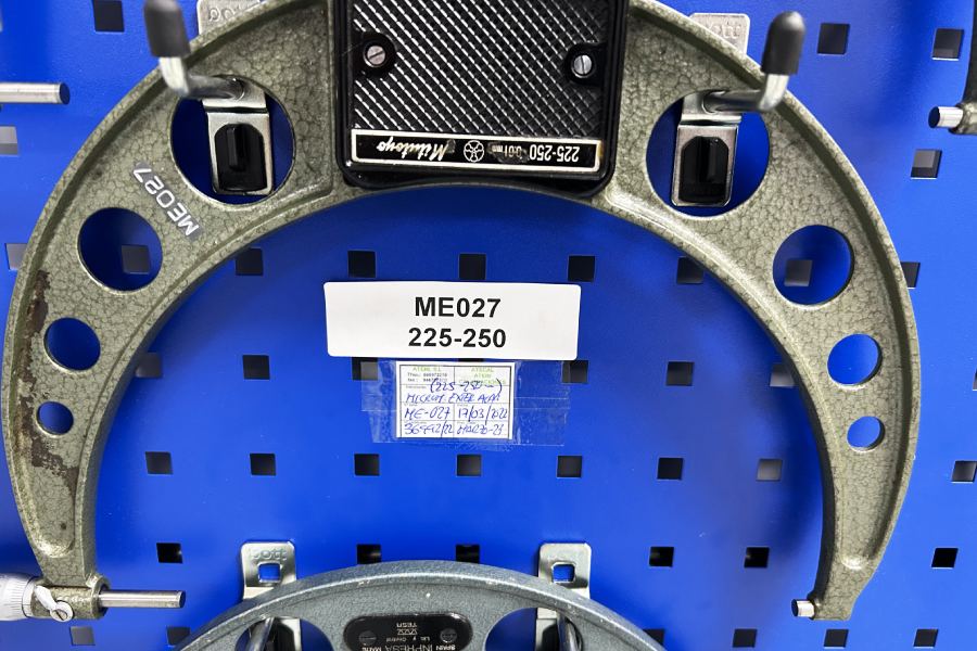
- External micrometres: control of dimensions with hundredth-/thousandth-level requirements.
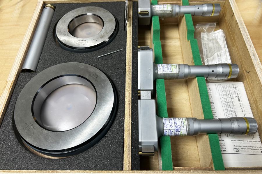
- Internal micrometres: control of internal diameters and critical fits.
- Alexometer: verification of housings and internal diameters in critical components.
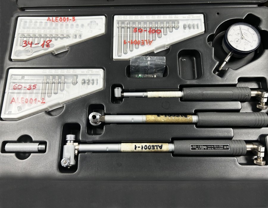
- Durometer: supporting control when the material and/or surface condition is relevant to the project.
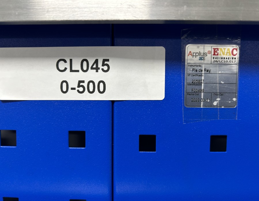
Traceability, calibration, and evidence for OEMs
All IMEs are stored and managed under controlled conditions. In addition, periodic external calibration is carried out by an accredited body (ENAC calibration) to ensure metrological traceability.
Each instrument is managed with identification and records, so evidence can be provided whenever the customer requests it:
- instrument and measurement range,
- serial number,
- calibration date,
- certificate number,
- next calibration due date.
In addition, measurement results are linked to other control areas, such as non-destructive testing, and to internal criteria for process stability. This way, dimensional control stops being “a one-off measurement” and becomes a way of working focused on preventing failures and rejections. As a result, certifications such as “How certification in non-destructive testing drives industrial quality” stop being just a stamp on paper and become part of day-to-day operations.
How IMEs fit into your value chain
If you are an OEM, quality manager or purchasing manager, the objective is not simply to “measure parts.” The objective is to reduce the cost of poor quality.
A well-implemented measurement system helps you:
- Reduce rejections and rework.
- Avoid surprises during assembly or testing.
- Improve process stability.
- Support audits with evidence.
- Make better supplier decisions.
- Identify dimensional drift before it becomes a non-conformity.
When required, tools such as Gage R&R studies or measurement uncertainty analysis can help formalize the reliability of the measurement system, especially for critical dimensions.
This is particularly important in components such as pump casings, covers, shafts and impellers. You can see how this connects with critical pump parts in our guide to centrifugal pump components and with supplier strategy in centrifugal pump machining.
Measuring instruments, CNC machining and technical welding
Measuring instruments become especially relevant when machining and welding are part of the same industrial process.
In machined parts, measurement confirms that the geometry produced by CNC machining matches the drawing and tolerances.
In this sense, CNC machining quality control depends not only on the machining process itself, but also on the measurement strategy, instrument calibration, inspection method and traceability of the results.
In welded components, measurement confirms whether distortion, material deposition, repair or overlay work has affected critical dimensions.
At Asimer Group, this connection between machining, welding and dimensional control is essential in projects involving pump, valve and compressor components.
Our teams combine engineering solutions, CNC machining, technical welding, metrology and documentation to support manufacturers that need reliable industrial components under drawing.
Do you need support in metrology and dimensional control?
If you are evaluating a supplier for machining, welding and verification of pump, valve or compressor components, the key question is:
Can they prove with data that they control what they deliver?
At Asimer Group, we help manufacturers reduce dimensional risk by combining CNC machining, technical welding, industrial metrology, dimensional reports and traceability in one controlled process.
Do you need support in dimensional measurement and verification?
Tell us which components you need to control — bodies, covers, shafts, impellers or trims — which tolerances are required by the OEM and what documentation you need, such as dimensional reports, calibrations or inspections. We will respond with a technical, not commercial, approach.
Request a dimensional control assessmentFrequently asked questions about measuring instruments in industrial metrology
1) Which measuring instruments are most commonly used in industrial metrology?
It depends on the feature and the tolerance. Quick checks typically rely on calipers and micrometers. Runout, alignment, and small variations are usually verified with dial indicators. For critical internal diameters, a bore gauge is commonly used. And when advanced dimensional control or a full report is required, 3D solutions come into play such as a CMM or a 3D measuring arm.
2) What’s the difference between measuring instruments and industrial metrology?
Instruments are the “means.” Industrial metrology is the system: method, conditions, calibration, traceability, and acceptance criteria. You can have good instruments and still generate dimensional measurement errors if there’s no procedure and no control of conditions.
3) What is metrological traceability, and why does an OEM request it?
Metrological traceability means being able to demonstrate that a measurement is linked to recognized standards through calibrations and records. An OEM asks for it because it reduces disputes and risk: if there’s a rejection, you can justify with evidence what was measured, with which instrument, and in what condition.
4) How often should measuring instruments be calibrated?
There’s no single rule: it depends on the instrument type, frequency of use, and how critical the dimension is. In industrial environments, a periodic calibration plan is commonly used, supported by internal verifications. At Asimer Group, critical IMEs are managed with ENAC-accredited calibration when applicable, and with status records in the Metrology Room.
5) Why does temperature affect dimensional measurement so much?
Because both the part and the instrument expand. That’s why the common reference is around 20°C, and why the environment is controlled for critical dimensions. Measuring “hot” can distort the result and lead to rejections or fit issues during assembly.
6) How can you reduce the risk of dimensional measurement errors in machined components?
With four actions: a stable environment, a defined procedure, training, and correct instrument selection. Additionally, when a dimension is critical, it’s recommended to repeat the measurement and if the project requires it formalize reliability with a Gage R&R study and measurement uncertainty criteria.
7) What documentation can accompany a delivery to prove dimensional control?
Depending on the project: measurement records, instrument identification and calibration status, and even dimensional inspection reports when applicable. If integrity verification is also required, it can be complemented with non-destructive testing.
8) How are measuring instruments and CNC machining related in critical parts?
CNC generates the geometry; measurement confirms compliance with the drawing and tolerances. In parts such as casings, covers, shafts, or impellers, that verification prevents rework, OEM rejections, and issues such as leakage, cavitation, or vibration.