What is meant by centrifugal pump?
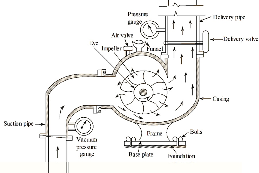
A centrifugal pump (centrifugal pump) is a hydraulic machine that transfers energy to the fluid by means of a rotating impeller which increases its speed; the housing (scroll or diffuser) converts this kinetic energy into pressure, raising the manometric height.
It is the most widely used equipment for moving low to medium viscosity liquids with high flow rates and continuous operation.
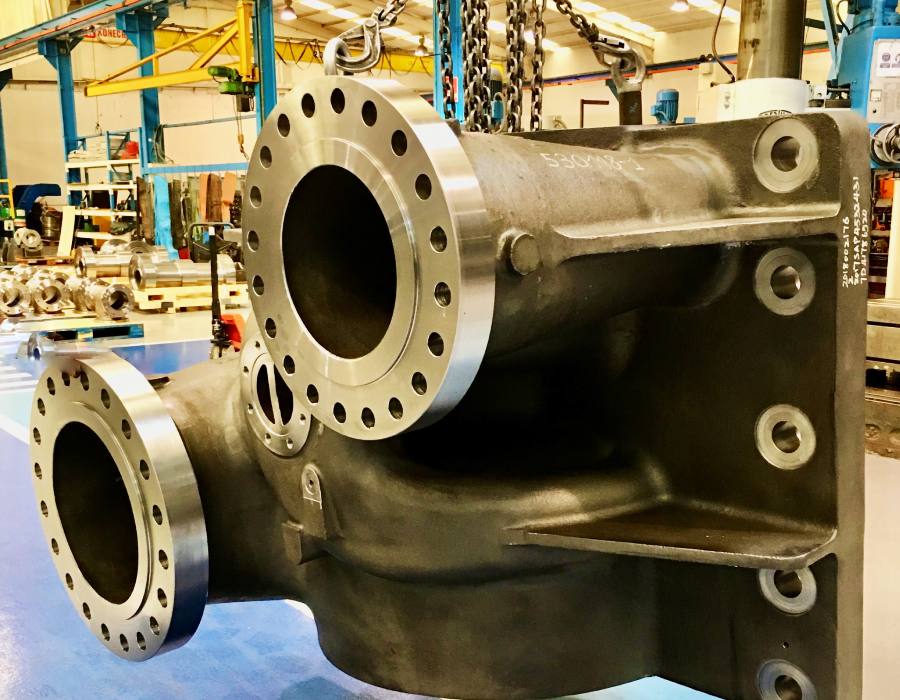
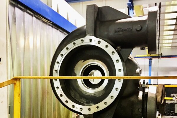
Basic components
- Impeller (impeller): provides energy to the fluid.
- Housing (scroll/diffuser): converts speed into pressure.
- Axle and bearings: transmit the engine torque and stabilize the assembly.
- Mechanical seal/plug: prevents leakage in the shaft passage.
- Base and coupling: alignment and assembly with the motor.
For a deeper explanation of the main centrifugal pump parts, their functions, materials and machining requirements, read our detailed guide on centrifugal pump components.
If you need to validate the selection and materials for your application, our engineering and machining production team can review your data sheet (Q, H, T, density, viscosity, solids, ATEX) and propose a solution
How do centrifugal pumps work?
A centrifugal pump converts engine energy into fluid energy by means of a rotating impeller that increases its speed. The housing (impeller or diffuser) then converts this kinetic energy into pressure, raising the total manometric height (H) and moving the fluid through the installation.
The liquid enters axially the impeller, acquires speed by the action of the blades and leaves radially towards the scroll/diffuser, where the speed is reduced and the pressure increases. A design with tight tolerances and good surface finish reduces internal losses and improves overall efficiency.
Operating point and Q–H curve (BEP)
- Define the flow rate (Q) and head (H) of the installation, and locate that point on the manufacturer’s Q–H curve.
- Prioritize operating close to the BEP (Best Efficiency Point) to minimize vibrations, recirculation, and wear.
- Avoid sustained operation too far to the left or right of the BEP, as it leads to efficiency losses and reduced service life.
NPSH and cavitation
- Calculate the system’s NPSHa (taking into account static load, losses and vapour pressure) and compare it with the pump’s NPSHr.
- Rule of thumb: leave a safety margin of 0,5-1,0 m between NPSHa and NPSHr.
- Reduces suction losses (dimensioned pipe, elbows away from the flange, low-loss valves) and controls fluid temperature to avoid approaching vapor pressure.
Efficiency and power
- Check performance at design point and dimensioning axle power: P_axis (ρ g Q H) / (η 1000)
- Considers hydraulic and mechanical efficiency (η) and applies margin/service of the engine according to operating conditions.
Materials, seals, and standards
- Select materials (e.g., CF8/CF8M, Duplex, Bronze) according to the fluid’s chemistry, temperature, and solids content, and specify the mechanical seal (single/double, cartridge) or packing as appropriate.
- Controlling tolerances and surface finish on impellers, shafts, and volutes through CNC machining reduces internal losses and brings operation closer to the BEP.
Selection and sizing for OEMs
Dimensioning a centrifugal pump requires: flow rate (Q), height (H), temperature, density, viscosity, solids, ATEX and operating regime.
Approximate Shaft Power
- P_shaft ≈ (ρ · g · Q · H) / (η · 1000)
- Add a margin to account for losses and process variations.
Minimum data checklist
- ATEX/approvals
- Fluid and temperature
- Q (m 3/h) and H (m)
- Estimated NPSHa and limitations in suction
- Preferred materials and compatibility
- Seal requirements (single, cartridge, API plan)
Standards and families
- API 610 (ISO 13709): refining and petroleum; strict mechanical requirements (seals, clearances, tests).
- EN 733 (DIN 24255): Scroll centrifuges for clean water, standardised dimensions.
- ISO 5199 / ISO 2858: Chemical process pumps; tolerances and materials for industrial service.
Materials and sealing
| Fluid / Condition | Casing / Impeller | Mechanical Seal | Note |
|---|---|---|---|
| Clean water 20–60 °C | EN-GJL / CF8 | Carbon / Ceramic | EN 733 |
| Moderate chemicals | CF8M / Duplex | SiC / SiC + Viton | ISO 5199 |
| Light abrasives | 316L + hardfacing | SiC / SiC (cartridge) | Add filtration |
| Cryogenic fluids | Low-temperature steel | Special cartridge seal | Specific clearances required |
Different types of centrifugal pumps
By type of flow
- Radial: greater manometric height at medium-low flow rates. Radial impeller, discharge perpendicular to the axis.
- Axial: very high flow rates at low heights. The flow follows the axis of the impeller.
- Mixed: compromise between height and flow; outlet with radial and axial component.
By number of stages
- Single stage: single wheel; general applications.
- Multi-stage: several wheels in series to raise the total pressure (boilers, osmosis, processes).
Other settings
- Self-primers: able to evacuate air in the suction without foot valve.
- Submersibles: integrated motor, operation under liquid level.
- Coil vs. diffuser: housing geometry that conditions performance and Q-H curve.
The standardization of families and variants accelerates the manufacture of components for centrifugal pumps and their integration into common platforms, reducing complexity and change times and enabling customizations without penalizing deadlines.
Materials of centrifugal pumps
There is a wide variety of construction materials, that go from various plastics and stamped cast iron or stainless steel for lighter duties, to bronzes, stainless steels, exotic alloys and specialty plastics for more corrosive, abrasive, hygienic or other difficult applications.
For hygienic or corrosive applications, the machining of stainless steel valves and pumps ensures tight tolerances, controlled surface finishes (Ra) and consistent passivation that prolong service life.
Uses and applications of centrifugal pumps
Typical applications for centrifugal pumps include:
- Low to medium viscosity liquids
- Chemical processes
- Food
- Pressure lubrication
- Pressure painting
- Cooling systems
- Service of oil burners
- Handling of grease
- Liquefied gases (propane, butane, (NH ), freon, etc.)
Grouping by sector (examples):
- Water and treatment: capture, drive, irrigation.
- Chemistry and process: acids/bases, solvents; compatible materials and seals.
- Food and beverage: CIP/SIP, 316L and hygienic finishes.
- Pulp and paper: low suspensions and process circuits.
- Cryogenics/LPG: propane/butane/liquefied ammonia; specific seals and clearances.
As we have detailed in point number 6, centrifugal pumps are also widely used in cooling systems that require extremely low temperatures, such as in cryogenic applications. These cooling systems often involve the manipulation of cryogenic gases, such as liquid nitrogen or liquid helium, to cool critical components in scientific research, semiconductor production and medicine. Centrifugal pumps are essential in these systems as they enable the transfer of high purity cryogenic liquids and gases and ensure a constant and uniform flow, helping to maintain the stability and accuracy of these critical cooling systems.
The industrial applications of centrifugal pumps include chemical processes, water and energy, food and beverages, pulp and paper, mining and cryogenics, where reliability, efficiency and asset availability are required. At extremely low temperatures, high-precision machining for cryogenic applications in industrial pumps and valves ensures adjustments and concentricity that prevent heat shrinkage leakage and loss of performance.
What are the main characteristics of a centrifugal pumps
There are two large families of pumps: centrifugal and positive displacement. Compared to the latter, centrifugal pumps are often specified for higher flow rates and to pump lower viscosity liquids. In some Chemical Plants, 90% of the pumps used are centrifugal. However, there are a number of applications for which positive displacement pumps are preferred.
Suitable for low to medium viscosity liquids; for highly viscous fluids or precise dosing, consider positive displacement.
What are the limitations of a centrifugal pump?
The centrifugal pump’s efficient working is based on the constant and high speed rotation of its impeller. Centrifugal pumps become increasingly inefficient with high viscosity feeds: there is a higher resistance and higher pressure is required to maintain a specific flow rate.
Sludge, such as sludge, or high viscosity oils can cause excessive erosion and overheating resulting damages and premature failures. Positive displacement pumps typically work at significant lower speeds and are less susceptible to these problems.
Another limitation is that, unlike a positive displacement pump, a centrifugal pump cannot suck dry: it must initially be primed with the pumped fluid. Therefore, centrifugal pumps are not suitable for any application where the supply is intermittent. Also, if the supply pressure is variable, a centrifugal pump produces a variable flow rate; a positive displacement pump is insensitive to pressure changes and will provide a constant output. Therefore, in applications where precise metering is required, a positive displacement pump is preferred.
Many of the limitations translate into failures in centrifugal pumps such as cavitation, misalignments, wear due to solids or losses by sealing; mitigating them requires a good hydraulic selection and precision machined components and materials suitable for the fluid.
Industry 4.0 and CNC machining of pumps
We apply the principles of Industry 4.0 CAM programming, traceability and verification to CNC machining of centrifugal pump housings (coils) and caps. In combination with controlled chip removal processes and strict tolerances, we reduce internal losses and bring the operation closer to BEP.
The digitalization of processes allows to optimize costs in the machining of pumps and valves by advanced CAM, statistical control, so we repeat critical geometries in short series with the same quality as in long series.
In addition, the machining of small series vs large volumes on industrial pumps is solved with modular tooling and multitask centers, maintaining concentricity, flatness and Ra target according to plan, without penalizing deadlines.
And when there are peaks in demand or launches, the outsourced machining centrifugal pumps provides additional capacity with the same traceability and quality standards, avoiding bottlenecks at plant.
TIG welding in centrifugal pump manufacturing
Tungsten Inert Gas (TIG) welding has become an indispensable technique in centrifugal pump manufacturing. This welding technique, which utilizes a tungsten electrode to generate the arc and an inert gas to shield the welding area, offers exceptional precision and high quality in joints. With TIG welding, a wide variety of materials can be welded, from stainless steel to exotic alloys, ensuring optimal strength and durability in centrifugal pumps.
Centrifugal pumps are essential in a wide range of industries, and their manufacturing requires precise welding techniques to ensure efficiency and durability. TIG welding has become the cutting-edge solution for the manufacturing of industrial pumps and valves, ensuring exceptional quality standards and optimal performance.
TIG welding is used to join key components of centrifugal pumps, such as casings, impellers, and shafts, ensuring structural and functional integrity without compromise. Thanks to its ability to produce clean and defect-free welds, TIG welding greatly contributes to the efficiency and reliability of centrifugal pumps in a wide range of industrial applications.
In chemical and marine environments, welding for corrosive environments combined with edge preparation by CNC and qualified processes (WPS/PQR) ensures homogeneous welds, minimal heat input and superior resistance to stress corrosion.
Services for centrifugal pumps at Asimer Group
Asimer Group supports OEMs and maintenance departments with applied engineering, CNC machining, welding and sub-plane centrifugal pump component inspection/assembly (housings/spirals, caps, diffusers, wear rings). As a machining company, we work with tolerances and finishes (Ra) defined in plan and traceability of materials and processes.
Capabilities
- Machining and inspection of critical components according to specification. Trevisan multitask centers and machining center for demanding diameters and geometries.
- TIG/MIG welding and recharging with qualified procedures (WPS/PQR/WPQ) and non-destructive tests (PT/VT/UT as requested).
- Assembly and testing when applicable, under instructions and customer requirements.
Quality and certifications
ISO 9001 and ISO 3834-2 (welding). Documentation and testing according to order requirements.
Operations and maintenance
- Predictive maintenance services for pumps and valves: after diagnosis, we recondition components and weld refills; apply NDT/NDT (e.g. PT/VT/UT) and dimensional verification in metrology according to project requirements.
- Initiatives to reduce the carbon footprint of industrial pumps and valves (improved performance and component life).
Send us your specifications (materials, tolerances, and process), and we’ll propose the most suitable machining/welding solution for your components.
Send specifications / RFQ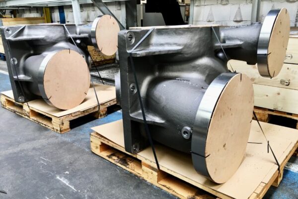
FAQs on centrifugal pumps
What types of centrifugal pumps are available?
Radial, axial and mixed; single stage or multi-stage; self-priming, submersible and scroll or diffuser housings.
How do I avoid cavitation?
Secures NPSHa > NPSHr with margin, optimizes suction line and controls temperature; selects suitable impeller and materials.
When to choose PD instead of centrifuge?
For highly viscous fluids, precise dosing or constant flow with pressure variations.