Accuracy machining means holding dimension, geometry, and surface finish according to drawing through CNC-based metrology (CMM/3D scanning), 5-axis machinery, and a stable process from CAD/CAM to batch release.
To achieve series CNC accuracy at Asimer Group, we combine dedicated fixturing, fewer re-clampings, intermediate verification, and batch traceability; when applicable, we reinforce control with SPC/Cpk. This way, we align design GD&T with dimensional control on the shop floor, integrating CAM → machine → CNC measurement systems.
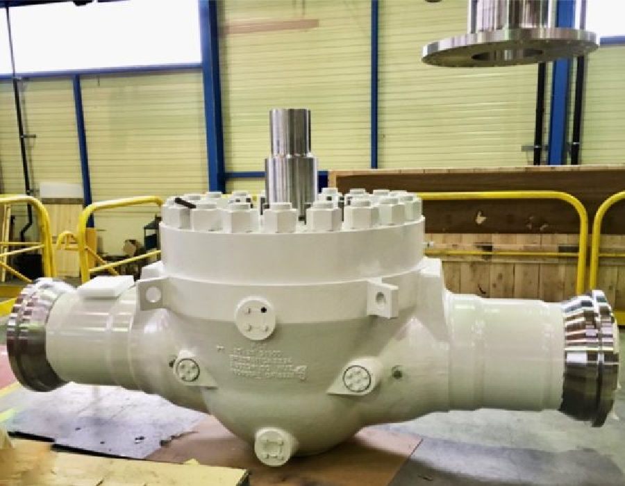
For those working with large bodies, covers, or bonnets under demanding tolerances, here we explain how we approach fixturing, datums, and alignment in the machining of large-dimension valves.
Accuracy machining: what it means and how it’s measured in CNC
Precision vital to any engineering development refers to the difference between the true value and your system’s measured value. If that difference is extremely small, the measurement is said to be highly accurate. It’s also described as the degree of conformity.
In addition, the term defines the reliability of a machine tool. Essentially, precision is a measure of a measurement system’s ability to return the same reading over and over again. Beyond that, it’s crucial that a measurement system be both accurate and precise.
In manufacturing, precision machining isn’t just “hitting a dimension”: it’s repeatedly meeting dimension, geometry, and surface finish. In CNC precision, this is designed with GD&T (flatness, roundness, parallelism, coaxiality/concentricity), prepared with stable fixturing and fewer re-clamps, and verified with a CNC measurement system (CMM and, where applicable, 3D scanning) correlated against the CAD model.
Accuracy depends on the combined machine–tool–fixture–workpiece system and the thermal environment (cooling, compensations). Repeatability is demonstrated with statistical process control (SPC/Cpk, where applicable) and batch-level traceability. This ensures that functional surfaces—seats, housings, gasket faces—achieve the required roughness (Ra) and tolerances demanded by their sealing or guiding function in pumps and valves.
What we measure and with what
- Dimension: micrometer/caliper and CMM on critical features.
- Geometry (GD&T): flatness, roundness, parallelism, and coaxiality with CMM (CAD comparison where applicable).
- Surface finish (Ra): roughness tester/profilometer according to the surface’s function.
- Repeatability: in-process sampling, SPC charts, and per-batch Cpk review.
Metrology Room and equipment
- Metrology Room with controlled environmental conditions for measurement stability.
- CMM for GD&T and critical dimensions; portable 3D measuring arm for on-machine checks and large formats.
- IMTE (inspection, measurement & test equipment): inside/outside micrometers, bore gauges, dial indicators, go/no-go gauges, and custom gauges.
- Measurement quality: equipment calibration and traceability; MSA (Gage R&R) studies where appropriate to support SPC/Cpk.
At ASIMER Group, we integrate these checks within the per-batch inspection plan and issue the associated metrology report for each work order, so setup, machining, and final inspection are linked in a single flow.
To delve deeper into the instruments and standards that underpin measurement quality on the shop floor, we detail our approach and criteria under Inspection and Measurement Instruments.
Impact of industry 4.0 on CNC machining accuracy
In precision machining, Industry 4.0 delivers real-time data that stabilizes the process and reduces variability. Capturing IoT signals (temperature, vibration, tool wear, spindle load) allows us to detect thermal drift and tool wear before they impact tolerance. With SPC/Cpk (where applicable) and batch traceability, we close the continuous-improvement loop and keep dimensional control per drawing.
How we run it on the shop floor
- IoT sensorization on the machine: monitors condition (temperature, vibration) and alerts on deviations.
- Automatic adjustments: tool compensation, re-zeroing, and offset updates to maintain coaxiality and flatness.
- CAD/CAM → machine → CNC metrology integration: the CMM—and, where appropriate, 3D scanning—compares parts against the CAD model and feeds back corrections to programs/parameters.
- SPC/Cpk and inspection plan: in-process sampling, control charts, and per-batch capability review.
At ASIMER Group, this digital framework lets us sustain CNC precision in short and medium runs, document every adjustment in the inspection plan, and link metrology results to each work order for complete traceability.
When the goal is also to reduce unplanned downtime and rejects due to dimensional drift, we integrate process and metrology data into condition-based plans and on-site support through our predictive maintenance services.
The role of automation in CNC machining accuracy
In precision machining, automation reduces variability and stabilizes the process. With 5-axis, in-machine probing, re-zeroing, and tool compensation, we maintain coaxiality, flatness, and parallelism across critical surfaces with fewer re-clamps—thereby lowering cumulative error part to part.
What we automate and why
- Fixturing and datums: dedicated tooling and master references to minimize repositioning error.
- In-machine probing: origin verification and misalignment correction before critical operations.
- Dynamic compensations: tool length/radius and automatic re-zeroing to contain thermal drift.
- Quick-change: reduces downtime and prevents manual misadjustments.
- Traceability: part/tooling codes to link CAD/CAM programs, tooling, and CMM reports to the batch.
At ASIMER Group, the combination of 5-axis centers and integrated probing cycles sustains CNC precision in short and medium runs with consistent dimensional control and lower operational risk.
As we scale from prototype to production, we apply automation to tune setups, thermal control, and cycle times—following the approach described in Small-batches vs. high-volume machining in industrial pumps.
Process, dimensional control and estimated lead time.
Strategies for improving dimensional tolerance in critical parts
Holding tight tolerances requires controlling the process, thermal behavior, and verification simultaneously. The starting point is CNC programming that minimizes re-clamping (5-axis when viable), defines a coherent datum, stable toolpaths, and parameters aligned with the material and the surface function (sealing, guiding, support).
Operational checklist (what we do and why)
- Fixturing and datums: dedicated tooling and master references to preserve coaxiality and flatness between operations.
- Thermal stability: cooling/lubrication management, thermal pauses when required, and re-zeroing to avoid dimensional drift.
- Toolpaths and stock allowance: semi-finishing with stock and finishing in isothermal passes, with in-cycle compensations (length/radius) to maintain tolerance; this approach is key to optimizing machining costs on pumps and valves without compromising accuracy.
- CNC cutting tools and workholding: use of tungsten carbide with suitable coatings (e.g., TiAlN/AlCrN on demanding materials) and balanced toolholders to reduce micro-burr formation and achieve the specified surface roughness (Ra).
- In-process and final verification: in-machine probing to readjust datums/offsets; CMM and, where applicable, 3D scanning against CAD before batch release.
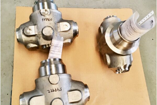
At ASIMER Group, the combination of stable fixturing, in-cycle compensation, and metrological verification (Metrology Room with CMM, portable 3D measuring arm, and IMTE) ensures that seats, housings, and gasket faces comply with the geometric tolerances (GD&T) and surface roughness (Ra) defined in the drawing, maintaining repeatability in short and medium series.
Advances in materials for high-accuracy CNC machining
In precision machining, the choice of workpiece and tool materials conditions dimensional stability and surface finish. Alloys such as stainless steel/duplex, superalloys, or titanium require specific strategies to contain thermal drift, avoid micro-burr formation, and achieve the required surface roughness (Ra).
What works and why (operational criteria)
- Workpiece material and stresses: consider thermal stability and residual stresses (stainless/duplex/titanium) to define toolpaths and semi-finishing with stock allowance before final finishing.
- Cutting tool: tungsten carbide substrates with suitable coatings (e.g., TiAlN/AlCrN for demanding materials) improve wear resistance and maintain tolerance stability across the batch.
- Geometries and toolholders: selection of insert geometry, nose radius, and balanced toolholders to reduce vibration and micro-burr formation, improving Ra control.
- Cooling/lubrication: coolant flow and orientation adapted to material and operation (deep drilling, cavity milling, seat finishing).
- Parameters coherent with coating: speed, feed, and depth of cut adjusted to the coating to avoid premature wear and dimensional scatter.
- Verification: in-machine probing where applicable and CMM/roughness-tester checks before batch release.
At ASIMER Group, we combine tool/coating selection, toolpaths with fewer re-clamps, and metrological control (Metrology Room, CMM, and 3D measuring arm) to ensure that seats, housings, and gasket faces comply with the geometric tolerances (GD&T) and Ra defined on the drawing.
In abrasive or corrosive environments, we complete the approach with surface coatings on the component itself to protect sealing areas and dimensional stability; we compare options in Types of coatings for industrial valves in extreme environments.
Quality control techniques to ensure accuracy in CNC machining
In precision machining, quality control sustains both accuracy and repeatability. At ASIMER Group, we verify against CAD using a CMM (coordinate measuring machine) and, where applicable, 3D scanning inside the Metrology Room to stabilize measurement uncertainty. We complement this with a roughness tester and IMTE (micrometers, bore gauges, calipers, dial indicators), and record results by batch.
What we verify and how
- Dimension (critical features): CMM and CAD comparison.
- Geometry (GD&T): flatness, roundness, parallelism, and coaxiality on the CMM.
- Surface finish (Ra): roughness tester on functional surfaces (sealing/guiding).
- In-process: in-machine probing to readjust datums/offsets before critical operations.
- Batch release: documented final inspection (inspection plan and traceability).
When function or material require it, we reinforce conformity with suitable NDT; for example, detecting surface-breaking discontinuities with Liquid Penetrant Testing, within the framework of Non-destructive test types applicable to pumps and valves. This confirms that seats, housings, and gasket faces meet GD&T and Ra specifications before batch release.
The importance of CAD/CAM software in CNC accuracy
In precision machining, CAD/CAM software is the core that connects design, process, and verification. Importing PMI/GD&T from the CAD model, defining stable strategies, and simulating the machine’s real kinematics allows us to anticipate collisions, reduce re-clamping, and maintain tolerance throughout the batch.
What CAD/CAM ensures for precision (in practice)
- Parametric tool libraries (geometry, nose radius, lengths) and cutting conditions aligned with material and coating.
- 3+2 / 5-axis strategies and stock models to move from semi-finishing to finishing in isothermal passes and contain thermal drift.
- Simulation with the real machine (validated post-processor and kinematics) to avoid collisions, axis limits, and post errors.
- Probing cycles generated from CAM to set datums, verify references, and update offsets before critical operations.
- Consistent process sheets and setup sheets (tools, fixturing, torque values, references) to ensure reproducibility between shifts.
- CAM program version control and linkage with the inspection plan (control points and tolerances) to reinforce batch traceability.
At ASIMER Group, we version the CAM program, tooling, and CMM results so that what is programmed (CAM) and what is executed (machine) are validated against CAD in the Metrology Room, closing the loop of CAM → machine → measurement and maintaining drawing-compliant precision.
As a next step, we connect what is programmed in CAD/CAM and verified on the CMM with on-plant actions to sustain precision in service; we explain this in machining and welding for predictive industrial maintenance: solutions for pumps, valves, and compressors.
Tool life optimization to maintain accuracy in CNC machining
Dimensional, geometric, and surface finish (Ra) stability depends on the condition of the cutting tool and toolholder. Extending tool life without losing precision requires planned control of wear, vibration, and thermal drift both in setup and in process.
What we do to sustain precision and tool life
- Tool and coating selection: tungsten carbide substrates with suitable coatings (e.g., TiAlN/AlCrN for demanding materials) to improve wear resistance and maintain tolerance throughout the batch.
- Toolholders and runout: selection and balancing to minimize runout and vibration, reducing micro-burr formation and Ra variation.
- Parameter and cooling adjustment: speed/feed/depth consistent with the coating, and coolant/lubrication directed at the cutting zone to contain temperature and dimensional drift.
- In-machine measurement and compensation: tool length/radius checks with probing or tool cycles, plus in-cycle compensations before critical operations.
- Tool maintenance: scheduled inspection, regrinding when applicable, and batch-level life tracking to avoid unexpected “end-of-life” failures.
- Result verification: in-process probing and final CMM/roughness checks to confirm that edge quality translates into drawing-compliant GD&T and Ra.
When wear and vibration data start to affect capability, we stop reacting to failures and plan condition-based actions to sustain precision in series.
Factors that take part in the machining precision
Final accuracy depends on the combined machine–tool–fixturing–workpiece–environment system. These are the factors that influence it most, and how we control them to sustain tolerances and Ra according to the drawing.
Physical factors
The geometric accuracy of the machine (guides, spindles, squares) and the assembly of its components condition the machining result. Any deviation in straightness, flatness, or coaxiality can push the measurement out of range.
How we mitigate it: planned maintenance, periodic geometric verification, rigid fixturing, and master references to reduce repositioning errors. The aging and wear of kinematic elements are also controlled through inspection and adjustment plans.
Human factors
Operator expertise impacts repeatability: datum selection, fixture preparation, sequencing, and in-process validation.
How we mitigate it: standardized procedures, CAM setup sheets, in-machine probing before critical operations, and batch-level incident logging to feed back into the process.
Thermal deformation factors
Heat from cutting and the machine structure itself causes expansion in the machine, tooling, and workpiece. Without control, dimensions drift.
How we mitigate it: directed cooling/lubrication, isothermal finishing passes, thermal pauses where applicable, and automatic re-zeroing/compensation to contain dimensional drift.
Force deformation factors
During cutting, forces (clamping, gravity, tool load) can flex the workpiece/fixture and shift the reference.
How we mitigate it: dedicated fixturing with defined support points, fewer re-clamps (5-axis when viable), balanced toolholders, and cutting strategies that minimize lateral force.
CNC programming factors
Programming aligned with the material and surface function is key: stable datums, toolpaths that avoid cumulative error, semi-finishing with stock allowance, and finishing with appropriate parameters.
How we mitigate it: parametric CAD/CAM libraries, real-kinematics simulation, probing cycles generated from CAM, and setup sheets with fixturing/torque values.
Internal factors
Out-of-tolerance installations, expired equipment calibration, or a Metrology Room without environmental control increase measurement uncertainty.
How we mitigate it: controlled environment in metrology, CMM and 3D measuring arm for GD&T, roughness tester for Ra, batch-level traceability, and inspection reports associated with each work order; the detail of the equipment and standards we use is compiled under Inspection and Measurement Instruments.
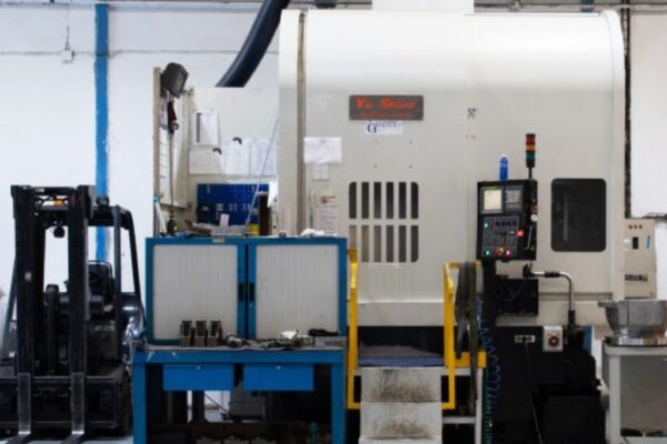
Machinery at Asimer Group
Our machine–tooling–process configuration is geared toward precision machining with fewer re-clamps, stable fixturing, and integrated verification (probing/CMM). This is how each equipment family contributes to holding dimension, GD&T, and Ra to drawing.
Trevisan machining centers
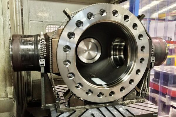
We consolidate critical operations (facing, boring, drilling) in a single setup to preserve coaxiality between housings and gasket faces. The facing/boring head and thermal management enable consistent finishes on large-format parts.
When tackling large valve bodies and actuators, concentrating operations on a single datum is decisive; that’s why we expand on this in Large-dimension valve machining.
CNC vertical lathes
For large-diameter components, the vertical configuration stabilizes mass and facilitates control of concentricity and squareness between flanges, seats, and housings. We integrate probing to establish datums and readjust offsets before each finishing pass.
In high pressure/temperature contexts and demanding media, this is the approach we apply in high-precision machining for the Oil & Gas sector.
CNC horizontal machining centers
Horizontal machines deliver productivity with palletization/4th axis while maintaining master references between opposing faces. We use them to consolidate semi-finishing with stock allowance and isothermal finishing, containing dimensional drift batch to batch.
In rotating and hydraulic assemblies, this strategy translates into functional precision and in-service performance.
CNC horizontal lathes
Suited for shafts, rotors, and flanges, with runout control and edge quality to minimize micro-burrs before sealing operations. Balanced toolholders and directed coolant help sustain the target Ra.
In stainless steels and corrosion-resistant alloys, we carry these criteria over to the machining of valves and pumps in stainless steel.
Asimer Group’s Technical Department gathers specifications and requirements, defines tooling and routes (CAD/CAM), coordinates suppliers where applicable, and manages batch logistics with traceability and a metrology report associated with each work order.
Process, dimensional control and estimated lead time.
Frequently Asked Questions (FAQ)
What is the difference between accuracy and repeatability in precision machining?
Accuracy is how close we get to the nominal value on the drawing; repeatability is how consistently we repeat it part after part. To sustain both, we combine CAD/CAM programming, stable fixturing, in-machine probing, and verification in the Metrology Room (CMM + roughness tester), according to our Inspection and Measurement Instruments (IMTE).
How is thermal drift controlled to maintain tolerance in series production?
Through directed cooling/lubrication, isothermal finishing passes, re-zeroing/compensations, and—where applicable—thermal pauses. On critical parts, fewer re-clamps (5-axis) preserve coaxiality and flatness. Extended tooling criteria are explained under CNC machining tools.
What role does CAD/CAM play in CNC precision?
It connects design–process–measurement: it defines stable strategies, simulates real machine kinematics, and generates probing cycles to set datums and update offsets. Parts are then checked against CAD using the CMM before batch release.
How do you select tooling and coatings without losing precision?
Start from the material and the function of the surface (sealing/guiding). In demanding applications, tungsten carbide tools with suitable coatings (e.g., TiAlN/AlCrN) are used, with cutting parameters and cooling/lubrication adjusted to contain wear and dimensional drift. As best practices, using balanced toolholders, adequate insert geometry/nose radius, and strategies that minimize vibration helps reduce micro-burrs and achieve the specified surface roughness (Ra).
When should non-destructive testing (NDT) be applied to machined components?
When function requires it (e.g., sealing surfaces), NDT complements metrology: for example, Liquid Penetrant Testing to detect surface-breaking discontinuities within the framework of Types of non-destructive tests before releasing the batch.
How do you decide between corrective and predictive maintenance to stabilize quality?
In precision machining, the decision is data-driven: if tool wear, runout, or vibration begin to degrade capability (greater tolerance or Ra dispersion), it’s advisable to shift from failure-based intervention to condition-based plans (wear thresholds, tool life tracking, vibration alarms, and metrological verification prior to finishing). A practical comparison of scenarios, cost, and availability is developed in our predictive maintenance guide for machining, where we contrast when it pays off versus corrective approaches.